Connecting Ethernet Cables
When you deploy the system (see Deploying the System), you connect:
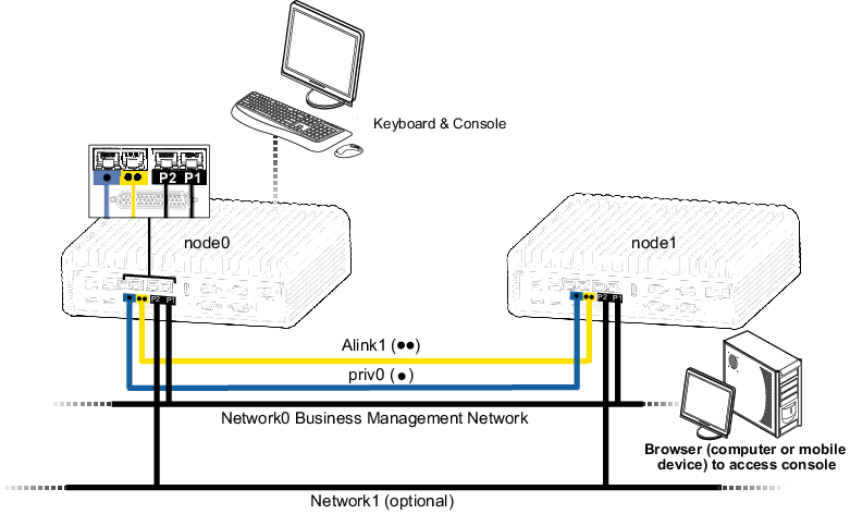
- The blue cable for priv0 from the blue embedded port (• or A2 on some systems) on node0 to the same embedded port on node1.
- The yellow cable for A-Link1 from yellow embedded port (•• or A1 on some systems) on node0 to the same embedded port on node1.
For network0 (ibiz0), you connect an Ethernet cable from P1 on each node to a network that is accessible from the remote management computer. For the optional network1 (ibiz1), you can connect an Ethernet cable from P2 on each node to the additional network.
Make any changes in your network (if necessary) in preparation for these connections. Then, perform the next step in Deploying the System.