Creating the Configuration
To create
A Typical ztC Edge System
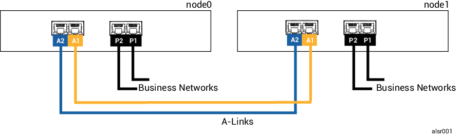
The physical distance between the PMs in a typical configuration is limited by the length of a single A-Link network cable, which is approximately 33 ft (10m). This distance may be significantly shorter when the physical environment and ambient electrical noise is accounted for.
An ALSR Configuration With a Quorum Server
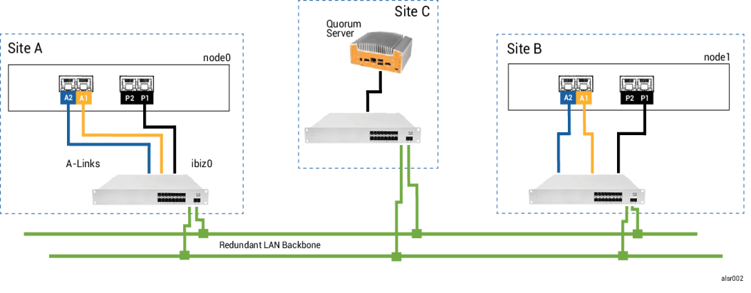
A well-planned ALSR configuration consists of the two nodes at two different locations, and a third computer that runs the quorum service at a third location. All of these computers are networked together with appropriate network switching equipment, so that no single point of failure exists within the ALSR configuration. The following figure illustrates such a configuration, which includes node0 at Site A, node1 at Site B, and the quorum server at Site C.
- Each A-Link should be connected on its own VLAN configured between switch A and switch B.
- DNS servers and gateways are not included in the illustrations, for clarity, but you must ensure that the ALSR configuration includes a connection to a DNS server and a gateway in the event of a network failure.
- For maximum protection, you should install redundant switches at each at site though the illustration does not show these switches. For the illustrated configuration, site A and site B would each include two switches. The A-Links are routed through one switch and the business networks are routed through the other switch. If possible, use different circuits to power the switches or use a UPS to prevent brief power loss failures.
ALSR VLAN Requirements
The A-Link connections between switch A and switch B require a VLAN configuration on the switches. A-Link traffic is not routable, and the connection should emulate a single long network cable. Each A-Link must be isolated on its own VLAN.
If you cannot create VLANs between the switching equipment, you can use Ethernet-to-fiber media converters to create a longer fiber connection between the two PMs. However, you should not route the two A-Link fiber connections through the same physical conduit, as this creates a single point of failure.
Additionally, the quorum service computer should not share a switch with either node0 or node1 because a shared switch creates a single point of failure.
See Meeting Network Requirements for more information about the latency requirements of the A-Links and quorum connections.
From Initial Deployment to Completing the ALSR Configuration
After the typical system is operating normally, create the ALSR configuration.
- Read Creating an ALSR Configuration and all of its subtopics, if you have not already done so.
- Install the quorum computer and enable the quorum server. Comply with all information in:
- Verify that the quorum server has access to both nodes.
- Properly shutdown one node. See Shutting Down a Physical Machine.
-
Relocate the shutdown node to the far site.
-
Connect the infrastructure. The ALSR-configuration illustration above shows the connections, which include:
- The priv0 connection to port A2
- The second A-Link connection to port A1
- The ibiz0 connection to port P1
-
Power on and (re-)join the nodes.
-
Verify the configuration. Ensure that:
- The shared networks pair properly—In the ztC Edge Console, navigate to the Networks page and ensure that the state of each network is green-checked. If necessary, troubleshoot any infrastructure problems.
- Quorum connections are remade—In the console, navigate to the Quorum Servers page by clicking Preferences and then Quorum Servers. Ensure that the state of the quorum server is green-checked. If necessary, troubleshoot any infrastructure problems.
- The primary node can shift from node0 to node1, and the console can connect in both configurations—Place each node in Maintenance Mode (see Maintenance Mode).
-
(Re-)join the VMs—Migrate the VMs from node to node (see Migrating a Physical Machine or Virtual Machine to a System). Verify the correct network failover of VM networking.
- Assess the status of network and validate Ethernet failover (see the Networks Page).