Connecting Power
To connect power, connect a single-node ztC Edge system to a single power supply, or configure a dual-node ztC Edge system with redundant power supplies connected to separate sources. You can optionally use site
After connecting power, return to Deploying the System.
Connecting ztC Edge 200i and 250i Systems to Site DC Power (Optional)
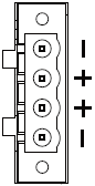
If you install a ztC Edge 200i or 250i system in an environment that provides DC power, you need to supply a power source at 9 to 36 VDC and a power cord with the correct wiring for each node. The following illustration shows the pin assignments for the DC input power connector on each 200i or 250i node.
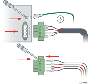
If you are connecting a node to a site DC power supply with user-supplied materials, fasten four separate wires (two positive (+) and two negative (-) wires) from the DC power supply to the power connector terminals. The wires must be a minimum of 18 AWG with a maximum length of 5 ft (1.5m). If the wire length is more than 5 ft (1.5m), increase the wire gauge for a maximum voltage drop of 1 V at 6.5 A. For best results, also terminate each wire with a ferrule sized and crimped as specified by the ferrule manufacturer. The following illustration shows the recommended signal ground, AC power adapter, and optional site DC power connections.
For additional system specifications, see System Specifications.
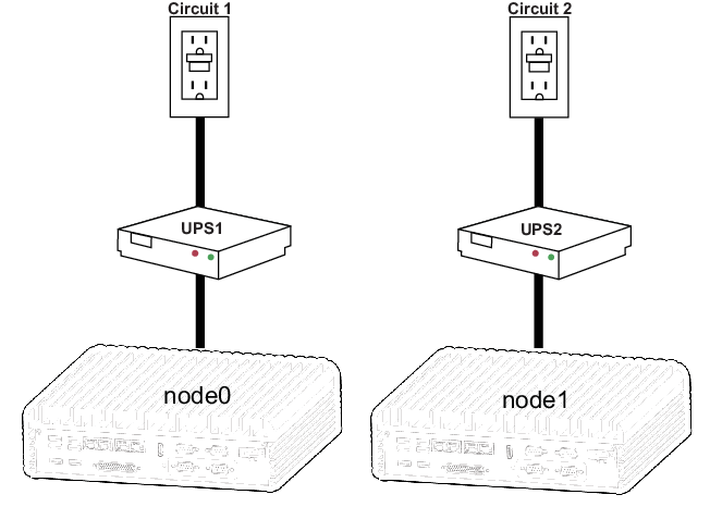
Connecting a ztC Edge System to UPS Power (Optional)
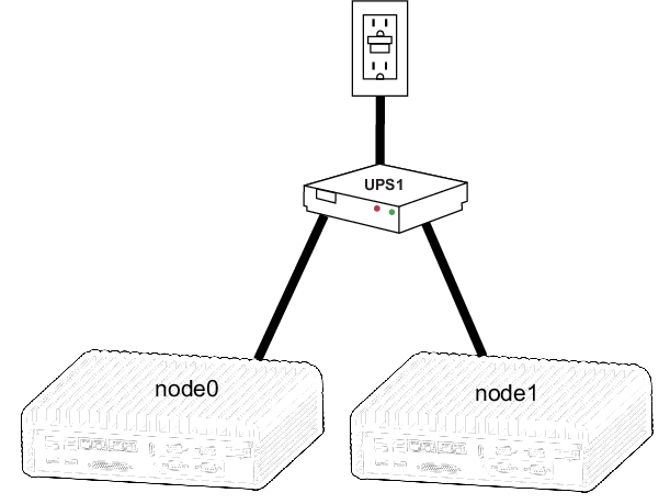
The following illustrations show how to connect one or two optional UPS units to a dual-node ztC Edge system. For an illustration of how to connect a single-node system to a UPS, see the node0 connections under Dual UPS.
Single UPS:
Dual UPS: